Gas Struts

Part Number
|
Rod ø
|
Tube ø | Length | Stroke | Force | Valve | Material Code | Mounting Thread | Stock | |||
|---|---|---|---|---|---|---|---|---|---|---|---|---|
| R | T | L | St | F1 | M | Available | ||||||
| [mm] | [mm] | [mm] | [mm] | [N] | [mm] |
|
||||||
| 0GS-N04BCZ0040 | 4 | 12 | 152 | 60 | 40 | No | N-Series (Nitrider) | 4 |
|
Details / Prices | ||
| 0GS-N04BCZ0070 | 4 | 12 | 152 | 60 | 70 | No | N-Series (Nitrider) | 4 |
|
Details / Prices | ||
| 0GS-N04BCZ0100 | 4 | 12 | 152 | 60 | 100 | No | N-Series (Nitrider) | 4 |
|
Details / Prices | ||
| 0GS-N04EAD0040 | 4 | 12 | 200 | 80 | 40 | No | N-Series (Nitrider) | 4 |
|
Details / Prices | ||
| 0GS-N04EAD0070 | 4 | 12 | 200 | 80 | 70 | No | N-Series (Nitrider) | 4 |
|
Details / Prices | ||
| 0GS-N04EAD0100 | 4 | 12 | 200 | 80 | 100 | No | N-Series (Nitrider) | 4 |
|
Details / Prices | ||
| 0GS-N04FAH0040 | 4 | 12 | 249 | 100 | 40 | No | N-Series (Nitrider) | 4 |
|
Details / Prices | ||
| 0GS-N04FAH0070 | 4 | 12 | 249 | 100 | 70 | No | N-Series (Nitrider) | 4 |
|
Details / Prices | ||
| 0GS-N04FAH0100 | 4 | 12 | 249 | 100 | 100 | No | N-Series (Nitrider) | 4 |
|
Details / Prices | ||
| 0GS-N04YCY0040 | 4 | 12 | 100 | 20 | 40 | No | N-Series (Nitrider) | 4 |
|
Details / Prices | ||
| 0GS-N04YCY0070 | 4 | 12 | 100 | 20 | 70 | No | N-Series (Nitrider) | 4 |
|
Details / Prices | ||
| 0GS-N04YCY0100 | 4 | 12 | 100 | 20 | 100 | No | N-Series (Nitrider) | 4 |
|
Details / Prices |
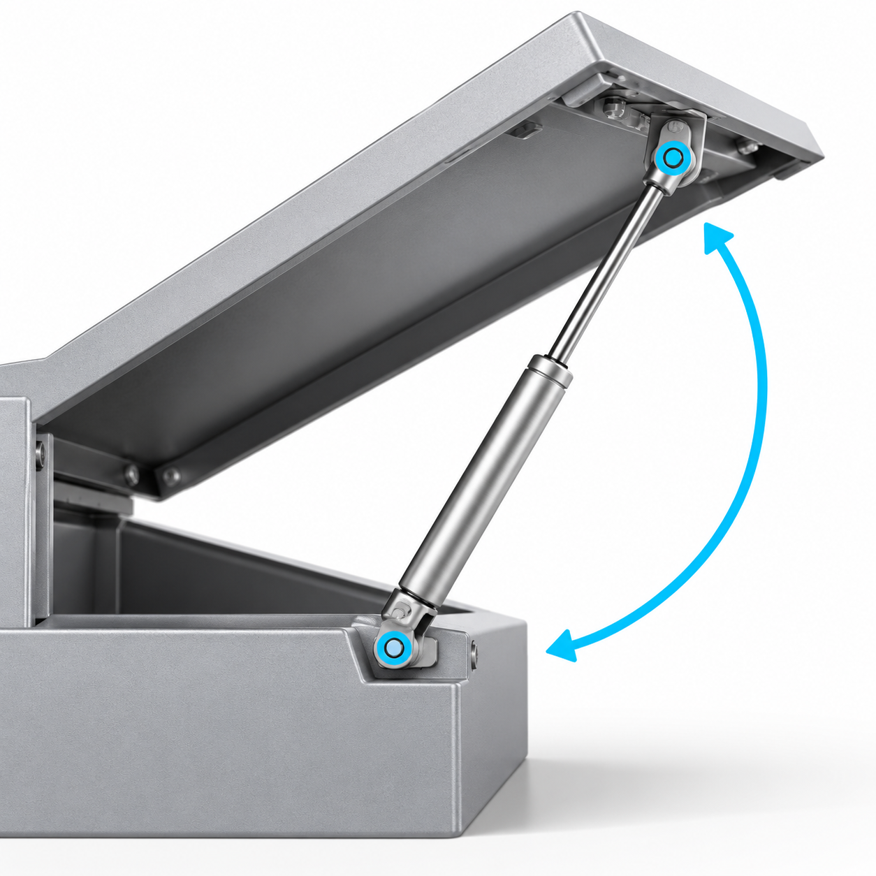 Design a flap or lid ›
Determine mounting points, required spring force and operating force for flaps and lids.
Design a flap or lid ›
Determine mounting points, required spring force and operating force for flaps and lids.
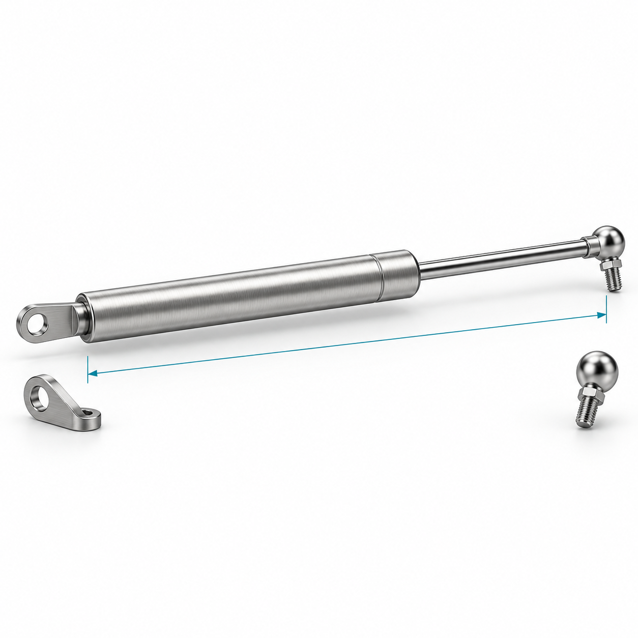 Configure a gas strut ›
Find catalogue gas struts by length, stroke and extension force, then select suitable end fittings.
Configure a gas strut ›
Find catalogue gas struts by length, stroke and extension force, then select suitable end fittings.
Gas Springs with Threaded Connections for Lifting, Holding and Supporting
Gas springs with threaded connections assist with the controlled opening, lifting, holding and lowering of flaps, lids and movable components. Pressurised nitrogen inside the cylinder extends the piston rod. An oil filling lubricates the seals and, depending on the installation position and design, supports end-of-stroke damping.
The threaded connections allow different end fittings, such as ball joints, fork heads or eye ends, to be installed. This makes it possible to adapt the same gas spring to different mounting arrangements.
Use the product table above to select a suitable version by piston rod diameter, cylinder diameter, extended length, stroke, spring force, valve, series and connection thread.
Meaning of the Specifications in the Product Table
| Specification | Meaning |
|---|---|
| Piston rod diameter R | Diameter of the extending piston rod. It influences the overall size, possible spring force and resistance to buckling. |
| Cylinder diameter T | Outside diameter of the pressure tube and therefore an important dimension for the available radial installation space. |
| Length L | Length of the fully extended gas spring according to the product drawing, usually without screwed-on end fittings. |
| Maximum stroke St | Maximum usable movement of the piston rod. The gas spring must not be used as a mechanical end stop. |
| Spring force F1 | Nominal extension force measured near the fully extended position and at the specified reference temperature. |
| Valve | Indicates whether the gas spring has a release valve for subsequently reducing the spring force. |
| Series | Identifies the material and design: N and V series with coated pressure tubes, and S and X series in stainless steel. |
| Connection thread M | Thread size for fitting compatible end connections. |
| Total stock | Total quantity of the article currently held in stock. |
| Available immediately | Quantity currently ready for immediate dispatch. |
Screwed-on end fittings change the overall installation length between the mounting points and must be considered separately during design.
Differences Between the N, V, S and X Series
Nitrider® N Series
The N series has a fixed spring force, a black-coated pressure tube and a nitrided piston rod. It is suitable for a wide range of applications in mechanical engineering, vehicle construction, furniture production and technical flaps or covers.
The required spring force is specified when ordering. As the gas spring is filled to the selected force, the value should be determined as accurately as possible before purchase.
Varilift® V Series
The V series is based on the N series but includes a release valve. It is supplied with a higher initial force, which can then be reduced gradually until the required force is reached.
This series is particularly suitable for prototypes, small production quantities or applications where friction, centre of gravity and operating feel cannot be determined accurately by calculation. The valve can only be used to release pressure. The force cannot be increased again by the user.
Stainless Steel S Series
The S series has a fixed spring force and is intended for applications with increased requirements for corrosion resistance and cleanliness. Typical applications include food and medical equipment, marine engineering and humid or demanding industrial environments.
The suitability of the stainless steel version for a particular medium must be assessed according to the actual operating conditions.
Stainless Steel Varilift® X Series
The X series combines a stainless steel design with a release valve. It is suitable for corrosion-exposed applications where the required spring force needs to be adjusted precisely during installation or testing.
How to Select the Right Gas Spring
Proceed in the following order:
-
Determine the installation lengths: Measure the distance between the mounting points with the application fully open and fully closed.
-
Define the required stroke: The required movement must remain within the maximum stroke St. Allow sufficient reserve so that the gas spring does not reach its internal end position.
-
Determine the spring force: Consider the weight, centre-of-gravity distance, lever arm, installation angle and number of gas springs.
-
Select the series: Choose N or S where the required force is known, and V or X where the force needs to be reduced during testing.
-
Check the installation space: Verify the piston rod diameter R, cylinder diameter T and possible interference throughout the complete movement.
-
Select the end fittings: Choose suitable end fittings according to the connection thread, movement direction and mounting points.
-
Consider the environment: Check temperature, humidity, dust, cleaning agents and other surrounding media.
The required spring force cannot be determined from the weight of the flap alone. The position of the centre of gravity and the mounting points have a major influence on the required torque.
Spring Force and Force Characteristics
F1 is the nominal force near the fully extended position. When the piston rod is compressed, the gas is compressed further, causing the spring force to increase over the stroke.
Friction also occurs at the seals. The forces during compression, standstill and extension therefore differ slightly. For correct design, the complete behaviour of the application must be considered rather than F1 alone.
The nominal force is usually specified at 20°C. It increases as the temperature rises and decreases as the temperature falls. As a guideline, the force changes by approximately three per cent for every 10°C change in temperature. The permissible operating temperature must be checked for the individual article and application.
Installation and Safety Recommendations
Gas springs are under high internal pressure and must not be opened, drilled, heated or mechanically modified.
For reliable operation, we recommend:
-
installing the gas spring with the piston rod pointing downwards when the application is closed, wherever possible,
-
avoiding lateral loads, misalignment and twisting,
-
using ball joints for moving mounting points where appropriate,
-
screwing end fittings fully onto the connection thread,
-
protecting the piston rod against scratches, dirt, paint and damage,
-
allowing sufficient stroke reserve,
-
using two gas springs symmetrically on wide or heavy flaps.
Where failure could endanger people, additional mechanical safety devices are required.
Suitable ball joints, fork heads, eye ends and other connection parts can be found in our gas spring end fittings.
Custom Spring Force and Returns
Gas springs with a fixed force are filled according to the force in newtons selected when ordering. This creates a customised product that normally cannot be returned.
Where the required force is not yet known, a V or X series gas spring with a release valve is recommended. Pressure should only be released in small increments, and the function should be checked again after each adjustment.
Further information on design, calculation, installation position and maintenance can be found in our Gas Spring FAQ.
Frequently Asked Questions About Gas Springs with Threaded Connections
What does the spring force F1 mean?
F1 is the nominal extension force of the gas spring near the fully extended position. The force increases as the gas spring is compressed.
Can the force be adjusted afterwards?
The N and S series have a fixed force. The V and X series include a release valve that allows the force to be reduced gradually.
Are the end fittings included in dimension L?
Dimension L refers to the gas spring as shown in the product drawing. Screwed-on end fittings increase the total length between the mounting points and must be considered separately.
Why should the piston rod point downwards?
This installation position helps keep the seal lubricated and allows the end-of-stroke damping to function more reliably. Other installation positions should be assessed technically.
Can the gas spring be used as an end stop?
No. The application requires separate mechanical end stops and sufficient stroke reserve.