EN 16983 (DIN 2093) & Belleville Disc Springs

Part Number
|
Outer ø
|
Inner ø | Thickness | Unloaded Length | Reduced Thickness | Loaded Length | Force at Length L1 | Standard | Disc Spring Group | Material Code | Stock | |||
|---|---|---|---|---|---|---|---|---|---|---|---|---|---|---|
| Da | Di | t | L0 | t´ | L1 | F1 | Available | |||||||
| [mm] | [mm] | [mm] | [mm] | [mm] | [mm] | [N] |
|
|||||||
| 0B0187-007 | 4.75 | 2.36 | 0.17 | 0.33 | 0 | 0.25 | 30.25 | Belleville | 1.1248 |
|
Details / Prices | |||
| 0B0187-007-S | 4.75 | 2.36 | 0.17 | 0.33 | 0 | 0.25 | 30.05 | Belleville | 1.4310 |
|
Details / Prices | |||
| 0B0187-010 | 4.75 | 2.36 | 0.25 | 0.38 | 0 | 0.32 | 68.05 | Belleville | 1.1248 |
|
Details / Prices | |||
| 0B0187-010-S | 4.75 | 2.36 | 0.25 | 0.38 | 0 | 0.32 | 68.05 | Belleville | 1.4310 |
|
Details / Prices | |||
| 0S4201 | 6 | 3.2 | 0.3 | 0.45 | 0 | 0.34 | 119 | ~ EN16983(2093) | 1 | 1.1231 |
|
Details / Prices | ||
| 0S4201E | 6 | 3.2 | 0.3 | 0.45 | 0 | 0.34 | 110 | ~ EN16983(2093) | 1.4310 |
|
Details / Prices | |||
| 0B0250-009 | 6.35 | 3.18 | 0.22 | 0.44 | 0 | 0.33 | 52.05 | Belleville | 1.1248 |
|
Details / Prices | |||
| 0B0250-009-S | 6.35 | 3.18 | 0.22 | 0.44 | 0 | 0.33 | 52.05 | Belleville | 1.4310 |
|
Details / Prices | |||
| 0B0250-013 | 6.35 | 3.18 | 0.34 | 0.51 | 0 | 0.43 | 117 | Belleville | 1.1248 |
|
Details / Prices | |||
| 0B0250-013-S | 6.35 | 3.18 | 0.34 | 0.51 | 0 | 0.43 | 115.7 | Belleville | 1.4310 |
|
Details / Prices | |||
| 0B0281-010 | 7.14 | 3.51 | 0.25 | 0.51 | 0 | 0.38 | 66.75 | Belleville | 1.1248 |
|
Details / Prices | |||
| 0B0281-013 | 7.14 | 3.51 | 0.33 | 0.53 | 0 | 0.43 | 109 | Belleville | 1.1248 |
|
Details / Prices |
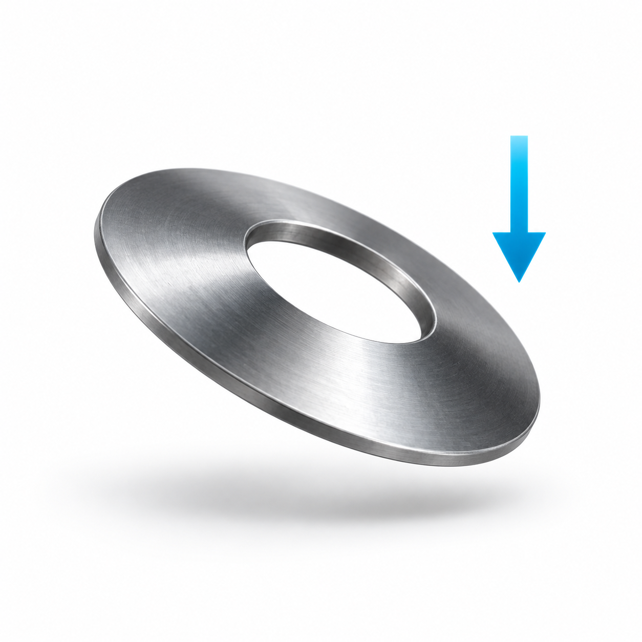 Design an individual disc spring ›
Find an individual catalogue disc spring by installed height, spring travel and target force.
Design an individual disc spring ›
Find an individual catalogue disc spring by installed height, spring travel and target force.
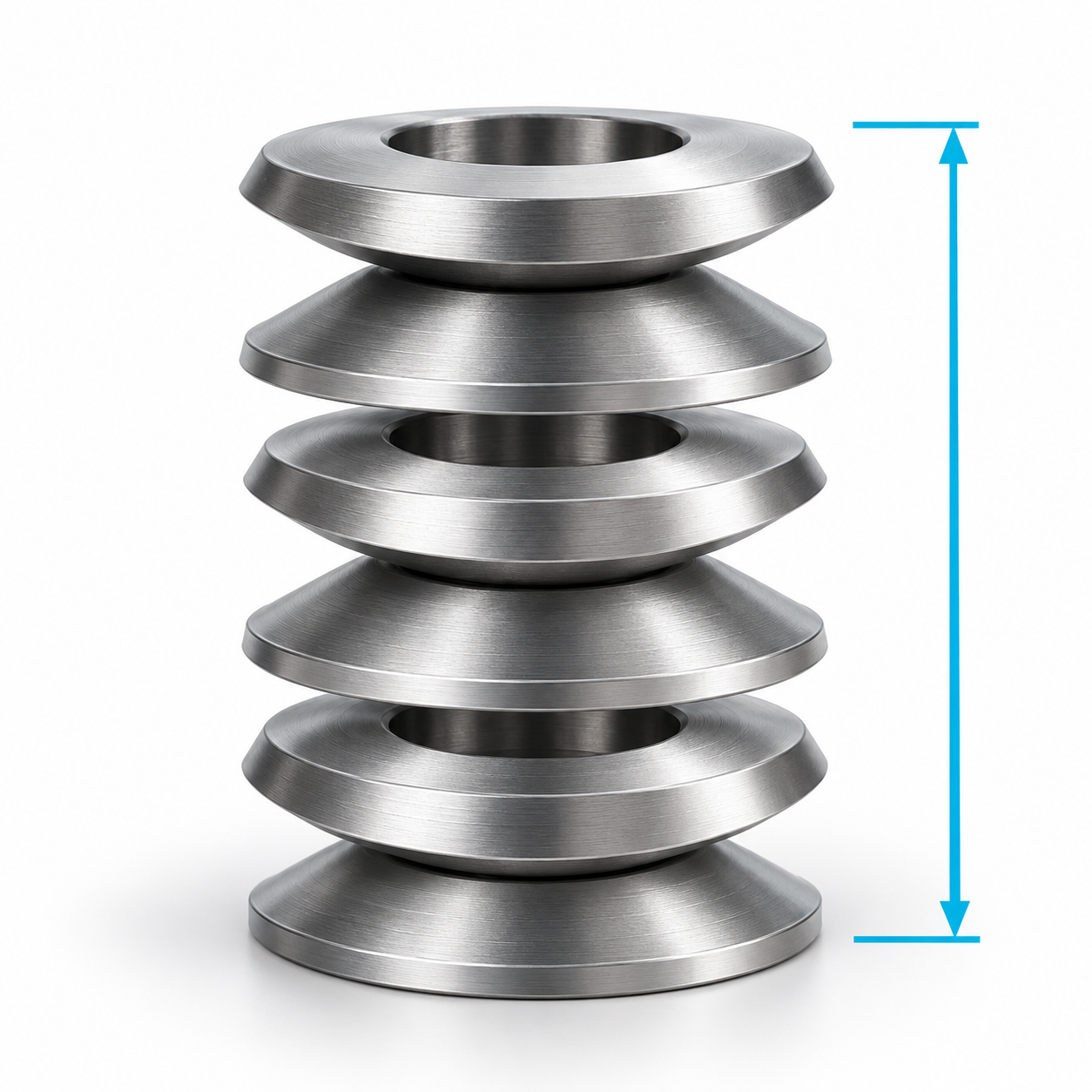 Design a disc spring stack ›
Calculate the force and travel of a stack of disc springs arranged in parallel or in series.
Design a disc spring stack ›
Calculate the force and travel of a stack of disc springs arranged in parallel or in series.
Disc Springs to DIN EN 16983 and Belleville Disc Springs
Disc springs are conically shaped annular washers that are loaded in the axial direction. They can generate high spring forces while requiring only a small installation height and comparatively short spring travel. By combining several disc springs, the spring force, spring travel and load-deflection characteristic can be adapted to different applications.
The Febrotec range includes metric disc springs manufactured to or similar to DIN EN 16983, the successor standard to DIN 2093, as well as Belleville disc springs in imperial dimensions. The Belleville versions complement the metric range with additional intermediate and inch-based sizes.
Use the product table above to select suitable disc springs by outside diameter, inside diameter, material thickness, free height, test height, spring force, standard, group and material.
Meaning of the Specifications in the Product Table
| Specification | Meaning |
|---|---|
| Outside diameter Da | Maximum outside diameter of the disc spring. It determines the required radial installation space and must be considered where external guidance is used. |
| Inside diameter Di | Diameter of the central opening. It must be suitable for the guide mandrel, shaft or adjacent component. |
| Material thickness t | Nominal thickness of the disc spring. It influences the spring force, spring travel and load capacity. |
| Free height L0 | Height of the unloaded disc spring. |
| Reduced material thickness t′ | For certain versions with machined bearing surfaces, the material thickness is reduced by design. Where no reduction is provided, the value is stated as 0. |
| Test height L1 | Defined compressed height at which the spring force F1 is tested and specified. |
| Force at L1, F1 | Axial spring force generated at the corresponding test height L1. |
| Standard | Identifies a version manufactured to or similar to DIN EN 16983 or a Belleville disc spring in imperial dimensions. |
| Group | Classification of standardised disc springs according to material thickness and design. |
| Material | Material from which the disc spring is manufactured. |
| Total stock | Total quantity of the article currently held in stock. |
| Available immediately | Quantity currently available for immediate dispatch. |
The test height L1 and spring force F1 must always be considered together. The value F1 applies only at the specified height L1.
Spring Travel and Spring Force
The spring travel to the specified test point is calculated as follows:
s1 = L0 − L1
where:
-
s1 = spring travel to the test height,
-
L0 = free height,
-
L1 = test height.
The spring force of a disc spring does not always increase linearly during compression. The load-deflection characteristic depends, among other factors, on the ratio between the free cone height and the material thickness.
The force F1 specified at the corresponding height L1 should therefore be used as the primary value for product selection. A calculation based on a constant spring rate is not sufficiently accurate over the complete spring travel of a disc spring.
DIN and Belleville Disc Springs
Disc Springs to DIN EN 16983
DIN EN 16983 specifies quality requirements and dimensions for disc springs. It replaces the former DIN 2093, whose technical content was incorporated into the European standard.
The standardised dimensional series simplify selection and replacement within a defined size. Depending on their design, the disc springs are assigned to different series and groups.
Belleville Disc Springs
Belleville disc springs are based on imperial dimensions. They may have different diameters, material thicknesses and proportions from comparable metric versions.
They are particularly suitable for:
-
designs using existing imperial dimensions,
-
replacing American or British disc springs,
-
intermediate sizes outside the metric standard range,
-
applications for which no suitable DIN EN size is available.
Belleville and metric disc springs must not be interchanged solely because their diameters are approximately the same. Material thickness, free height, test height and spring force must also be compared.
Series and Groups According to DIN EN 16983
For many standardised diameter combinations, three series are available:
-
Series A: high spring force with comparatively short spring travel,
-
Series B: medium spring force and medium spring travel,
-
Series C: lower spring force with greater spring travel.
The groups mainly relate to material thickness and manufacturing or machining method:
-
Group 1: thin disc springs with a thickness below 1.25 mm,
-
Group 2: disc springs from 1.25 mm up to and including 6 mm,
-
Group 3: disc springs over 6 mm and up to 14 mm.
The permissible force and dimensional tolerances vary depending on the group and dimensions. The information for the individual product and the applicable standard is decisive.
How to Select the Right Disc Spring
Proceed in the following order:
-
Determine the installation space: Define the maximum outside diameter Da, required inside diameter Di and available axial installation height.
-
Define the spring force: Determine the required force at the intended operating point.
-
Calculate the spring travel: Establish the difference between the free height and the working height.
-
Compare the test point: Select a disc spring whose F1 and L1 values are as close as possible to the intended operating point.
-
Consider the type of loading: Distinguish between static, occasionally cycled and dynamic loading.
-
Select a single spring or stack: Determine whether one disc spring is sufficient or whether several springs need to be combined.
-
Select the material: Consider corrosion, temperature, contact with media and the required service life.
-
Define guidance and lubrication: Disc spring stacks must be guided adequately, and sliding contact surfaces may require lubrication.
For dynamic applications, a disc spring should not regularly be compressed to the completely flat position. The permissible working range must be checked for the individual design.
Stacking Disc Springs
Several disc springs can be arranged in series, in parallel or in a combined configuration.
Parallel Stacking
With parallel stacking, the disc springs face in the same direction.
The forces are approximately added together, while the spring travel remains equal to that of a single disc spring:
-
two springs in parallel: approximately twice the force,
-
three springs in parallel: approximately three times the force.
Friction occurs between the contacting surfaces. The actual compression and return forces may therefore differ from the calculated total.
Series Stacking
With series stacking, the disc springs are arranged alternately in opposite directions.
The spring travels are added together, while the force remains approximately equal to that of a single disc spring:
-
two springs in series: approximately twice the spring travel,
-
three springs in series: approximately three times the spring travel.
Combined Stacking
Parallel and series groups can be combined. This makes it possible to increase both the spring force and the total spring travel.
However, as the number of disc springs increases, friction, tolerance effects and the requirements for guidance and lubrication also increase. The stack should therefore be designed using as few springs as reasonably possible.
Guidance, Lubrication and Installation
Disc springs and disc spring stacks require flat and sufficiently hard supporting surfaces. Depending on the design, guidance may be provided at the inside or outside diameter.
For reliable operation, we recommend:
-
providing sufficient clearance between the spring and guide,
-
using flat and parallel supporting surfaces,
-
applying the load evenly in the axial direction,
-
avoiding lateral forces and tilting,
-
using suitable lubrication for stacked disc springs,
-
limiting the spring travel with mechanical stops,
-
testing the stack under actual installation conditions.
Suitable lubrication reduces friction, wear and heat generation between disc springs stacked in parallel. Depending on the application and environment, oil, grease or an appropriate solid lubricant may be used.
Materials and Corrosion Protection
Depending on the dimensions, the standard range includes disc springs manufactured from spring steels such as 1.1231, 1.1248 and 1.8159, as well as stainless spring steels 1.4310 and 1.4568.
Disc springs manufactured from carbon or alloy spring steel are often supplied phosphated and oiled. This treatment provides limited protection during storage and operation in dry or moderately exposed environments.
Stainless spring steels are intended for applications with increased corrosion-resistance requirements. Their suitability for chlorides, seawater, acids or elevated temperatures must be assessed according to the actual operating conditions.
Frequently Asked Questions About Disc Springs
What is the difference between DIN and Belleville disc springs?
DIN EN disc springs have standardised metric dimensions. Belleville disc springs are based on imperial dimensions and extend the range with additional sizes and proportions.
What do L0, L1 and F1 mean?
L0 is the free height. L1 is the defined compressed test height. F1 is the spring force generated at this height.
How can the force of a disc spring stack be increased?
By stacking the disc springs in parallel. The forces of the individual springs are approximately added together.
How can the total spring travel be increased?
By stacking the disc springs in series. The spring travels of the individual springs are approximately added together.
Can different disc springs be combined?
Combining different dimensions or materials should only be done after technical calculation. Identical disc springs should generally be used within one stack.
Further information on standards, stacking arrangements and technical design can be found in our Disc Spring FAQ.