Torsion Springs

Part Number
|
Wire ø
|
Outer ø | Max. Torque | Max. Torsion | Max. Mandrel ø | Leg Length | Active Coils | Direction | Material Code | Stock | |||
|---|---|---|---|---|---|---|---|---|---|---|---|---|---|
| d | Da | Md | alpha | M/S | E | n | Available | ||||||
| [mm] | [mm] | [Nmm] | [°] | [mm] | [mm] |
|
|||||||
| 0T012-090-055 | 0.3 | 2.36 | 5.31 | 57.2 | 1.4 | 9.52 | 2.25 | 90° | 1.4310 |
|
Details / Prices | ||
| 0T012-090-055L | 0.3 | 2.36 | 5.31 | 57.2 | 1.4 | 9.52 | 2.25 | 90° | 1.4310 |
|
Details / Prices | ||
| 0T012-180-067 | 0.3 | 2.77 | 5.31 | 152.3 | 1.7 | 9.52 | 5 | 180° | 1.4310 |
|
Details / Prices | ||
| 0T012-180-067L | 0.3 | 2.77 | 5.31 | 152.3 | 1.7 | 9.52 | 5 | 180° | 1.4310 |
|
Details / Prices | ||
| 0T012-180-109 | 0.3 | 4.22 | 5.31 | 145 | 2.77 | 12.7 | 3 | 180° | 1.4310 |
|
Details / Prices | ||
| 0T012-180-109L | 0.3 | 4.22 | 5.31 | 145 | 2.77 | 12.7 | 3 | 180° | 1.4310 |
|
Details / Prices | ||
| 0T012-270-062 | 0.3 | 2.59 | 5.31 | 247.1 | 1.57 | 9.52 | 8.75 | 270° | 1.4310 |
|
Details / Prices | ||
| 0T012-270-062L | 0.3 | 2.59 | 5.31 | 247.1 | 1.57 | 9.52 | 8.75 | 270° | 1.4310 |
|
Details / Prices | ||
| 0T012-270-109 | 0.3 | 4.32 | 5.31 | 235.4 | 2.77 | 12.7 | 4.75 | 270° | 1.4310 |
|
Details / Prices | ||
| 0T012-270-109L | 0.3 | 4.32 | 5.31 | 235.4 | 2.77 | 12.7 | 4.75 | 270° | 1.4310 |
|
Details / Prices | ||
| 0T012-360-109 | 0.3 | 4.42 | 5.31 | 330.2 | 2.77 | 12.7 | 6.5 | 360° | 1.4310 |
|
Details / Prices | ||
| 0T012-360-109L | 0.3 | 4.42 | 5.31 | 330.2 | 2.77 | 12.7 | 6.5 | 360° | 1.4310 |
|
Details / Prices |
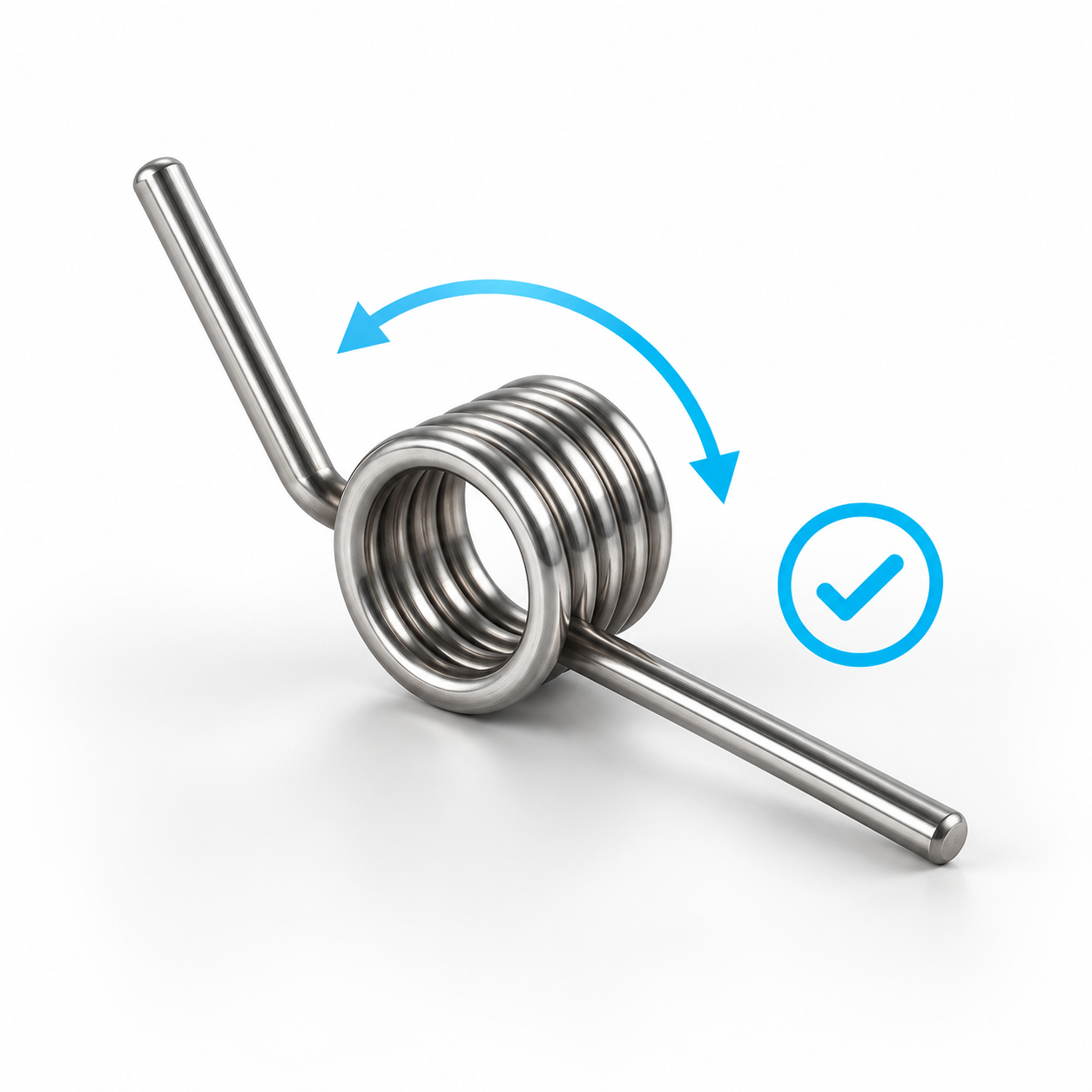 Select a torsion spring ›
Find torsion springs that match your rotation angle, leg position and torque.
Select a torsion spring ›
Find torsion springs that match your rotation angle, leg position and torque.
Torsion Springs and Leg Springs for Rotary Movements
Torsion springs, also known as leg springs or rotational springs, generate torque when their legs are rotated relative to each other. They store mechanical energy during deflection and release it again when unloaded. This allows flaps to be opened or closed, levers to be returned and movable components to be held in a defined position.
A torsion spring consists of a coiled spring body and two legs through which the torque is applied. The standard versions have straight legs and are available with different leg positions and in right-hand or left-hand wound designs.
Typical applications include hinges, flaps, levers, switches, tools, household appliances, vehicle components, medical devices and precision mechanical assemblies.
Meaning of the Specifications in the Product Table
| Specification | Meaning |
|---|---|
| Wire diameter d | Diameter of the spring wire. It influences torque, installation space and load capacity. |
| Outside diameter Da | Maximum outside diameter of the unloaded spring body. When loaded in the winding direction, the diameter decreases. |
| Maximum torque Md | Highest specified torque at the corresponding maximum deflection angle. This value is not automatically suitable as a continuous operating load in dynamic applications. |
| Maximum deflection angle α | Maximum intended angle between the initial position and the loaded position. |
| Maximum mandrel diameter M/S | Maximum recommended diameter of the guide mandrel or shaft when using the specified maximum deflection angle. |
| Leg length E | Length of the straight spring legs according to the product drawing. The effective force depends on the actual point of application. |
| Number of coils n | Number of active coils in the spring body. It influences the deflection angle, spring rate and axial length. |
| Leg position | Angle between the two legs in the unloaded condition, for example 90°, 180°, 270° or 360°. |
| Material | The standard springs offered are made from stainless spring steel 1.4310. |
| Total stock | Total quantity currently held in stock. |
| Available immediately | Quantity currently available for immediate dispatch. |
The maximum torque and maximum deflection angle are linked values. The stated torque is reached at the corresponding angle and must not be considered independently.
Torque and Leg Length
Torque describes the rotational effect of the spring. The force acting at the spring leg depends on the distance between the axis of rotation and the point of force application:
Force = torque ÷ effective lever arm
At the same torque, a longer lever arm produces a lower force. If the force is applied closer to the spring body, the resulting force increases.
The specified leg length E is therefore not necessarily identical to the effective lever arm. The decisive value is the actual distance between the spring axis and the point where the leg acts on the surrounding structure.
Right-Hand or Left-Hand Wound Torsion Spring
The winding direction must match the intended direction of loading. A torsion spring should be loaded so that its coils tighten and the diameter of the spring body decreases.
Loading the spring against its winding direction opens the coils. This creates less favourable stresses and may significantly reduce service life.
For an individual spring, check:
-
In which direction does the movable component rotate?
-
Which leg remains fixed?
-
Which leg moves?
-
Does the spring diameter decrease under load?
-
Is a right-hand or left-hand wound version required?
Mirror-image assemblies often use one right-hand and one left-hand wound spring as a pair. The required winding direction should always be checked against the product drawing and installation arrangement.
Selecting the Correct Leg Position
The leg position describes the angle between the two legs when the spring is unloaded.
A spring with a 90° leg position has legs arranged at right angles. At 180°, the legs point in opposite directions. A 270° position provides a larger angular offset. A 360° position means that the two legs are largely parallel in the initial condition.
The correct position depends on the location of the contact points in the unloaded condition and the required angle of rotation during operation.
How to Select the Correct Torsion Spring
Proceed in the following order:
-
Determine the required torque: Calculate the required force and effective lever arm.
-
Define the deflection angle: Determine the angle between the unloaded and maximum loaded positions.
-
Select the leg position: The initial position must suit the geometry of the application.
-
Check the winding direction: The spring must be loaded in the direction of its coils.
-
Check the installation space: Compare the outside diameter, leg length and axial length with the available space.
-
Select the mandrel: The shaft diameter must not exceed the specified M/S value.
-
Assess the type of loading: Distinguish between static, occasional and frequently alternating loads.
-
Consider the environment: Check humidity, temperature, cleaning agents and other surrounding media.
In dynamic applications, the maximum catalogue torque should not be used continuously. A significant reduction in operating load is recommended where a long service life is required.
Installation and Guidance
Torsion springs are normally guided over a mandrel, shaft or pin. Sufficient clearance must remain between the spring inside diameter and the guide, even at maximum deflection.
When the spring is loaded in its winding direction, its diameter decreases. At the same time, the axial length of the spring body may increase. Sufficient lateral clearance must therefore also be provided.
For reliable operation:
-
load the spring only in its intended winding direction,
-
avoid lateral forces and misalignment,
-
support both legs securely and over a suitable contact area,
-
provide sufficient radial and axial clearance,
-
use mechanical stops to prevent overloading,
-
do not exceed the specified torque or deflection angle,
-
test the function over the complete movement range.
The legs should not be shortened, bent, welded or subsequently heated without technical assessment. Such modifications may affect the material properties and spring characteristics.
Stainless Spring Steel 1.4310
The standard versions are made from stainless spring steel 1.4310. This material combines good spring properties with increased corrosion resistance and is suitable for many industrial applications.
Due to cold working, 1.4310 may become slightly magnetic. Suitability must be assessed separately for permanent exposure to seawater, chlorides, acids or aggressive cleaning agents.
Custom torsion springs with different leg shapes, dimensions or materials can also be requested.
Frequently Asked Questions About Torsion Springs
In which direction may the spring be loaded?
It should be loaded in its winding direction so that the coils tighten and the spring body diameter decreases.
Is Md the force acting at the leg?
No. Md is the torque. The force at the leg depends on the torque and the effective lever arm.
What does M/S mean?
M/S indicates the maximum recommended mandrel or shaft diameter when using the specified deflection angle.
Can a torsion spring be used without a mandrel?
This depends on the design. However, suitable guidance improves positioning and helps prevent lateral movement or buckling.
Are customised versions available?
Yes. Different leg lengths, leg positions, end shapes, materials and dimensions can be supplied as custom-made torsion springs.
Further information about winding direction, leg position and installation can be found in our torsion spring FAQ.